UXGNEP
Buckling under Compression Forces Test/Experiment
Objective
The objective of this experiment is to determine the buckling loads for solid and hollow with various lengths when subjected to axial compression forces.
Introduction
A column with an applied force will
eventually deform as the force increases. Several factors influence the critical buckling load: length of the column, support conditions, the location
of the load relative to centroid of the axis and the shape of the cross section. The deflection of an elastic column is given by:
Where:
M(x) is bending moment;
E is the modulus of elasticity;
I is the moment of inertia of the cross section;
x is the distance of a point on the beam;
y is the deflection;
For the situation when the two ends of the column are pinned, we assume that the load is centric and the column only deforms elastically, we have Euler’s formula which calculates the theoretical critical buckling load:
Where:
Pcr is the critical buckling load;
L is the column’s effective length;
The following formula allows computing the critical normal stress:
Where:
r is the radius of gyration: ;
A is the cross sectional area;
λ is the slenderness ratio( )
When the support conditions are different, the effective length of the column (Le) should be used in the equations above to replace the value L. The effective length is determined by multiplying the column length L by the effective length factor K. For situation when where there is one fixed end, one free end, K=2. When one end is fixed, the other is pinned, K=. When both ends are fixed, K=0.5.
(source: lab manual)
In reality, the assumptions that are made for the Euler’s formula are usually not met. Experimental failure loads are usually lower than the theoretical value. Here we use design formulas for alloy 6061-T6, which is the material of the specimen in this lab
Equipment and specimens
1. Compression testing machine;
2. Load measuring devices;
3. Vernier calliper;
4. Aluminum tubes and rods with different lengths: 225mm, 125mm and 75 mm
Procedure
1. Measure the inner diameter and outer diameter of each specimen.
2. Start the experiment with the 225mm specimen first. Perform individual tests with each specimen for the following three conditions: both ends fixed, one end fixed with one pinned, and both ends pinned.
3. Apply load and gradually by increase the compressive force until an obvious deformation occur. Record the value of load.
4. Perform experiments on 125mm and 75mm specimen only under the condition when both ends are fixed
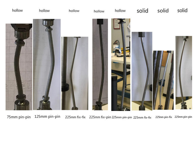
5. Sketch/take a picture of the mode of failure for each sample.
Analysis of the results
Sample calculations:
1.Cross sectional area:
For hollow column with 225 mm length and pin-fixed end:
For solid column with 225 mm length and pin-fixed end:
Moment of inertia:
For hollow column with 225 mm length and pin-fixed end:
For solid column with 225 mm length and pin-fixed end:
Radius of gyration:
For hollow column with 225 mm length and pin-fixed end:
2.
Effective length:
For hollow column with 225 mm length and pin-fixed end:
Critical load:
E=70*103 MPa
For hollow column with 225 mm length and pin-fixed end:
3. Experimental Critical Stress:
For hollow column with 225 mm length and pin-fixed end:
Slenderness ratio:
For hollow column with 225 mm length and pin-fixed end:
4. Theoretical Critical Stress:
For hollow column with 225 mm length and pin-fixed end:
Report
1.
|
Type of column |
Column length, L(mm) |
End condition |
Experimental critical load, Pcr (N) |
Experimental critical stress, σcr (MPa) |
|
|
Hollow |
75 |
pin-pin |
3796 |
249.9 |
|
|
125 |
pin-pin |
3210 |
213.29 |
||
|
225 |
pin-pin |
1480 |
97.69 |
||
|
225 |
pin-fixed |
1291 |
85.78 |
||
|
225 |
fixed-fixed |
2103 |
140.86 |
||
|
Solid |
225 |
pin-pin |
1585 |
51.01 |
|
|
225 |
pin-fixed |
1504 |
47.94 |
||
|
225 |
fixed-fixed |
2664 |
84.92 |
2&3
allowable stress:
for λ< 9.5: (1)
for 9.5 < λ < 66: (2)
for λ > 66: (3)
sample calculations :
For hollow column with 225 mm length and fixed-fixed end:
For solid column with 225 mm length and pin-fixed end:
Discussion
1. Comparing the theoretical and the experimental value of the critical stress we notice that their values are different. Many factors may cause these discrepancies. For example, the load was not gradually applied, the load was not perfectly centric, the material does not have an exact elastic modulus of 70Gpa, and the shape of the cross section is not perfectly uniform. Comparing the values, we notice that some experimental stress values are lower than the theoretical ones, others are higher.
2. Comparing values on the graph, we notice that the allowable stresses values recommended by the aluminum association are lower than both theoretical and experimental values. This is the expected result because the allowable stress should always be less than the stress at failure condition
3. Buckling strength of real columns is affected by many factors, for example, the radius of the cross section, the shape of the cross section, the location of the load relative to the central axis of the column, the actual elastic modulus of the tested material.
4.
The buckling load is proportional to I given other values are the same for both solid and tube specimens. Taking a solid bar (d=2mm) and a circular tube (dout=mm, din=1mm) as an example, they both have the same Area.
For circular tube:
For solid bar:
Itube is greater than Ibar, so the circular tube has a higher buckling load.
Conclusion
In this experiment, we have learned that buckling load depends on many factors such length of the column, the dimension of cross-section area, elastic modulus of the column and the support conditions. We have found that the experimental values are different that the theoretical values, and both of them are greater than the allowable stress values.
|
Type of column |
Column length, L(mm) |
End condition |
Effective length factor, k |
Effective length |
Inner diameter (mm) |
Outer diameter (mm) |
x-section-nal area |
Moment of inertia (mm4) |
Radius of gyration (mm) |
Slender-ness ratio, λ |
Allowable stress, σall (MPa) |
Theoretical critical load, Pcr (N) |
Theoretical critical stress, σcr (MPa) |
Experimental critical load, Pcr (N) |
Experimental critical stress, σcr (MPa) |
|
|
Hollow |
75 |
pin-pin |
1 |
75 |
4.58 |
6.35 |
15.19 |
58.21 |
1.96 |
38.27 |
105.78 |
7149.45 |
471.72 |
3796 |
249.9 |
|
|
125 |
pin-pin |
1 |
125 |
4.60 |
6.35 |
15.05 |
57.83 |
1.96 |
63.78 |
83.64 |
2557.00 |
169.84 |
3210 |
213.29 |
||
|
225 |
pin-pin |
1 |
225 |
4.60 |
6.36 |
15.15 |
58.33 |
1.96 |
114.80 |
26.63 |
796.02 |
52.42 |
1480 |
97.69 |
||
|
225 |
pin-fixed |
0.707 |
159.08 |
4.60 |
6.35 |
15.05 |
57.33 |
1.95 |
81.58 |
52.71 |
1565.12 |
103.81 |
1291 |
85.78 |
||
|
225 |
fixed-fixed |
0.5 |
112.5 |
4.63 |
6.36 |
14.93 |
57.76 |
1.97 |
57.11 |
89.43 |
3285.62 |
211.82 |
2103 |
140.86 |
||
|
Solid |
225 |
pin-pin |
1 |
225 |
6.29 |
31.07 |
76.84 |
1.57 |
143.31 |
17.09 |
1048.62 |
33.64 |
1585 |
51.01 |
||
|
225 |
pin-fixed |
0.707 |
159.08 |
6.32 |
31.37 |
78.31 |
1.58 |
100.68 |
34.63 |
2137.88 |
68.16 |
1504 |
47.94 |
|||
|
225 |
fixed-fixed |
0.5 |
112.5 |
6.32 |
31.37 |
78.31 |
1.58 |
71.20 |
69.24 |
4274.74 |
136.28 |
2664 |
84.92 |
|||
Ball Bearing and Roller Bearing Manufacturing Process and Technology
1. Introduction
A bearing is a machine element that enables rotational or linear movement, and reduces friction between different parts. Bearings are widely used in our lives today, for example, they are used in skateboards, fidget spinners, electric scooters, metro wagons, airplanes and so on. A study shows that people use at least 200 bearings per day. For example, we use bearing every day on the way to school: metro, cars or bicycles. On the way to our classroom: the escalator or the elevator. Even when we are just sitting and playing computer games, there are bearings running non-stop in our PCs to keep us entertained. The manufacturing process of ball bearings and roller bearings includes several steps that can take a couple of days to finish. This article explains each process in detail, and presents some new technologies in the bearing industry.
Ball bearings can support moderate radial loads and moderate axial loads (thrust load). They can operate at high speeds.
There are four types of ball bearings, they are:
- Deep groove ball bearings
- Angular contact ball bearings
- Self-aligning ball bearings
- Thrust ball bearings
2.2 Deep Groove Ball Bearings
The most common type of ball bearings are the deep groove ball bearings. A deep groove ball bearing is composed of an inner race, an outer race, steel balls that fit between the inner and outer, move along the track called raceway, and a cage that prevents the steel balls from falling out or contact in one another.
2.3 the Manufacturing Process of Deep Groove Ball Bearings
The manufacturing process of a deep groove ball bearing consists of:
1. Preparation of Bearing Materials
2. Forging
3. Turning
4. Heat Treatment
5. Grinding
6. Making of Steel Balls
7. Making of Retainers
6. Assembly
Preparation of Bearing Materials
Preparation of materials is the first step to make ball bearings. The steels are first heated to about 1710 degree Celsius to eliminate as many impurities as possible. Then the components are used to form high carbon chromium bearing steel, which has an extremely high tensile strength. Then it is formed to necessary shapes and sizes for the productions of different types of bearings. They are formed into wires, plates, tubes, bars and so on.
Forging
The steel bar is first heated then cut. It is then pressed by machine and molded into inner and outer ring shapes. The designated shapes are formed by hot forging.
Turning
For the turning of the inner ring, first, the surface on one side is cut, then the other. After that, the bore is cut. Then, it is chamfered. Finally, the raceway is cut, and the turning of the inner ring is completed. The turning of the outer ring is similar to that of the inner ring. The marks are stamped on the side surfaces of the ring indicating the information such as the brand and part number. Nowadays, more manufacturers are using laser marking machines.
Heat Treatment
Because the inner and outer rings work under tremendous pressure and they repeatedly go through rolling motions, they must be extremely rigid and wear-resistant. So, they have to go through quenching, which they are heated between 800 and 860 degrees Celsius, then instantly cooled. To boost wear resistance, they are held at 1450 to 200 degrees for a long period, they cooled slowly. This process is called tempering. Tempering must be done soon after quenching to reduce the risk of cracking.
Grinding
For the grinding of the outer ring, the side surface of the ring is first ground. Then the outer surface is ground so that it is precisely perpendicular to the side surface. Then using the outer surface as a reference, the raceway groove is honed. The same process applies to the inner ring.
Making of Steel Balls
The steel balls are more difficult to make even though their shape is very simple. To make steel balls, the wires are first cut and formed into spherical shapes between dies. Then the balls are continuously rolled to create smoother surfaces. After undergoing heat treatment, they are repeatedly polished with grindstones to improve their surface finish. Then their diameters are measured. They are sorted and delivered to the assembly plant. This entire process takes a few days.
Making of Retainers
The retainers for deep groove ball bearings are typically manufactured by press molding the steel plates.
Assembly
There are slight gaps between the inner and outer rings and the steel balls, which is known as the internal clearance. Different clearances apply to the bearings according to various applications. When a bearing is being assembled, the internal clearance is adjusted by selecting steel balls of different sizes. Nowadays, bearings are assembled by industrial robots. This machine is measuring the raceway dimensions between the inner and outer rings. That measurement determines which ball size is chosen. The machine then places the correct number of steel balls between the two rings. Retainers are placed above and below, and then riveted. The assembled units are cleaned. Then the grease is squeezed evenly into the raceway, then the bearings are sealed if necessary. Many manufacturers test the bearings before they ship out. For example, the durability, performance and noise level.
Roller bearings have high radial load capacity and some designs can accept light axial loading. They operate at moderate-to-high speeds.
There are five types of roller bearings, they are:
1. Tapered roller bearings
2. Cylindrical roller bearings
3. Needle roller bearings
4. Spherical roller bearings
5. Trust roller bearings
The most common type of roller bearings are the tapered roller bearings. Similar to a ball bearing, a tapered roller bearing is composed of an inner race, which is also called a cone, an outer race, which is also known as a cup, and a cage. Instead of steel balls, the rolling elements are the rollers.
3.3 the Manufacturing Process of Tapered Roller Bearings
The manufacturing process of a tapered roller bearing consists of:
1. Preparation of Bearing Materials
2. Forging
3. Turning
4. Heat Treatment
5. Grinding
6. Making of Rollers
7. Making of Retainers
6. Assembly
The manufacturing process of a tapered roller bearing is also very similar to that of a deep groove ball bearing. However, the processes of the cage, the rolling element are different.
Making of Rollers
Steel wires are die cut into cylinders to make the rollers. It then goes through several surface finishing and heat treatment processes.
Making of Retainers
Steel plates are first press cut into circles, then formed into cone shapes, the bottom is then cut. It then goes through a turning process. After that, rectangular sections are cut for the assembly of rollers.
4. New Technologies in the Bearing Industry
The technologies in the bearings industry have been developed in recent years. For example, ceramic ball bearings are made for the use under conditions of high speeds and high temperatures. The third generation of bearing hub units for passenger vehicles are pre-sealed, pre-greased and integrated with ABS for better performances. Another technology is the bearing unit with sensors used on high-speed trains. Such sensors monitor the rotational speed, acceleration and temperatures of the bearings in use, which makes great a contribution to safer transportation.
How to Reverse the Axis Order of a Chart in Excel
How to Reverse the Axis Order of a Chart in Excel
How to reverse the axis order of a chart in Excel? change the direction of axis display of chart axes Microsoft Office change a chart's orientation How to reverse the X or Y axis of time series data flip vertical horizontal axis bar scatter chart How to rotate Excel chart or worksheet एक्सेल में किसी चार्ट के अक्ष के क्रम को कैसे बदला जाए? चार्ट अक्ष के अक्ष प्रदर्शन की दिशा में परिवर्तन करें Microsoft Office एक चार्ट की ओरिएंटेशन बदलता है समय या एक्स अक्ष के डेटा अक्षरों को उल्टा कैसे बदल सकता है ऊर्ध्वाधर क्षैतिज अक्ष पट्टी स्कैटर चार्ट फ्लिप कैसे करें Excel चार्ट या वर्कशीट को कैसे घुमाने के लिए ¿Cómo revertir el orden del eje de un gráfico en Excel? cambiar la dirección de la visualización del eje de los ejes del gráfico Microsoft Office cambiar la orientación de un gráfico Cómo invertir el eje X o Y de la serie de datos flip vertical barra horizontal del eje gráfico de dispersión Cómo rotar el gráfico o la hoja de cálculo de Excel Excelでグラフの軸の順序を逆にする方法は? グラフ軸の軸表示の方向を変更するMicrosoft Officeグラフの向きを変更する時系列データのX軸またはY軸を反転する方法垂直軸の水平軸バー散布図を反転するExcelグラフまたはワークシートを回転する方法 如何在Excel中反轉圖表的軸順序? 更改圖表軸的軸顯示方向Microsoft Office更改圖表方向如何反轉時間序列數據的X或Y軸翻轉垂直水平軸條形圖散點圖如何旋轉Excel圖表或工作表 Comment inverser l'ordre des axes d'un graphique dans Excel? modifier la direction de l'affichage des axes des axes de graphique Microsoft Office modifier l'orientation d'un graphique Comment inverser l'axe X ou Y des données de séries temporelles retourner vertical diagramme de dispersion des barres d'axe horizontal Comment faire pivoter un graphique ou une feuille de calcul Excel Как изменить порядок оси диаграммы в Excel? изменить направление отображения оси осей диаграммы Microsoft Office изменить ориентацию диаграммы Как отменить ось X или Y данных временного ряда перевернуть вертикальную диаграмму рассеяния по горизонтальной оси Как вращать диаграмму или таблицу Excel এক্সেলের একটি চার্ট এর অক্ষ ক্রম বিপরীত কিভাবে? চার্ট অক্ষের অক্ষ প্রদর্শনের দিকটি পরিবর্তন করে মাইক্রোসফ্ট অফিস একটি লেখচিত্রের অভিযোজন পরিবর্তন করে সময় শৃঙ্খলের এক্স বা উল অক্ষের বিপরীত দিকে উল্লম্ব অনুভূমিক অক্ষ বার স্প্রেটার চার্ট উল্টানো কিভাবে এক্সেল চার্ট বা ওয়ার্কশীট ঘুরান ਐਕਸਲ ਵਿੱਚ ਇੱਕ ਚਾਰਟ ਦੇ ਧੁਰੇ ਨੂੰ ਕਿਵੇਂ ਉਲਟਾ ਕਰਨਾ ਹੈ? ਚੈਨਲਾਂ ਦੇ ਧੁਰੇ ਦੇ ਧੁਰੇ ਡਿਸਪਲੇਅ ਦੀ ਦਿਸ਼ਾ ਬਦਲਣਾ ਮਾਈਕ੍ਰੋਸੋਫਟ ਆਫਿਸ ਇਕ ਚਾਰਟ ਦੀ ਸਥਿਤੀ ਨੂੰ ਬਦਲਦਾ ਹੈ ਵਾਰ ਜਾਂ ਸੀਰੀਜ਼ ਦੇ ਐਕਸ ਜਾਂ ਉਲਟ ਐਕਸਰੀ ਨੂੰ ਕਿਵੇਂ ਉਤਾਰਿਆ ਜਾਵੇ ਵਰਟੀਕਲ ਅਰੀਜ਼ੈਂਟਲ ਐਕਸਿਕਸ ਬਾਰ ਸਕੈਟਰ ਚਾਰਟ ਨੂੰ ਕਿਵੇਂ ਬਦਲਣਾ ਐਕਸਲ ਚਾਰਟ ਜਾਂ ਵਰਕਸ਼ੀਟ ਨੂੰ ਕਿਵੇਂ ਘੁੰਮਾਉਣਾ ਹੈ